Core Tap Procedures for Storm and Sewer Mains
These procedures describe how to connect to existing storm and sewer mains and miscellaneous structures owned by Seattle Public Utilities (SPU) and the steps for scheduling a core tap.
SPU performs all work on existing City of Seattle sewer and drainage pipes and structures unless pre-authorized and observed by SPU. The permit holder is responsible for service piping to the tee or wye.
1.1 Contact SPU
- (206) 615-0511 to schedule core taps or to report an existing Tap Break-in (Hammer Tap)
- SPU_CORETAP_Scheduling@seattle.gov to submit drawings or permits
- (206) 386-1800 to report emergencies or pipe defects
1.2 New Connections to Existing Pipe
SPU reserves the right to determine placement of service connections. After permit issuance, SPU may refuse to perform the tap at the permit holder's proposed location based on field conditions.
SPU will core tap for service laterals 6-inch, 8-inch, and 10-inch diameter. Core taps for larger service laterals will be installed by the contractor and must be observed by SPU.
1.3 New Connections to New Pipe
Most new connections to new pipe are with a prefabricated tee. See the Standard Specifications.
2.1 When a core tap is not required
If a sewer or drainage service meets all other requirements of SPU and Seattle Department of Construction Inspections (SDCI), connections to existing active or inactive tees and wyes or stubs may be permitted and inspected by SDCI. The permit holder is responsible to:
- Locate the tee, wye or stub; and
- Ensure the connection is to the permitted discharge point (storm or sewer) to prevent cross connections; and
- Determine that the existing pipe and connection is in operative condition;
2.2 If existing damage and defects are observed
The permit holder is not responsible for repair of pre-existing defects on the host pipe, tee, or wye. If any defects in the existing wye or tee or exposed main are observed, the permit holder must notify SPU at (206) 386-1800, notify the SDCI site inspector, and take pictures of the defects.
When notified about existing defects, SPU may:
- Repair the defect
- Note the defect in City records and allow the permitted connection; or
- Provide an alternate connection point.
Call SPU at (206) 615-0511 to schedule a core tap. Inform the core tap scheduler if you have a permitted non-standard connection. You will also need to email an 8 ½” by 11” copy of the approved drawing and permit information to SPU_CORETAP_Scheduling@seattle.gov.
With all requests and documents provide the following information.
INFORMATION REQUIRED WHEN SCHEDULING
| SIDE SEWER PERMT FROM SDCI | CITY PROJECT or PERMIT FROM SDOT |
|---|---|
| Side Sewer Permit number | SDOT Street Improvement Permit number or Capital Improvement Project number |
| Contact name, email and phone number | Contact name, email and phone number |
| Company name of the Registered Side Sewer Contractor (RSSC) | Company name. Subcontractors also provide General Contractor Company Name |
| Address and cross streets | Address and cross streets |
| Tap Size and number of taps | Tap Size and number of taps |
| Lateral Pipe Material | Lateral Pipe Material |
| Drawing of approved non-standard connection | Drawing sheet showing detail or profile of any approved non-standard connection |
| Observations of mainline pipe condition (for example: size; material; high flow conditions) | Observations of mainline pipe condition (for example: size; material; high flow conditions) |
When scheduling, note that SPU requires more than 2 days' notice for tapping some pipe materials, non-standard connections, or other more complex situations.
MINIMUM NOTICE REQUIREMENTS
| TYPE OF TAP/MAINLINE MATERIAL | NOTICE REQUIRED |
|---|---|
| Tap on Asbestos Cement | 10- business days |
| Tap on Corrugated Metal Pipe | 10- business days |
| Tap or Observation on the Weekend or at Night | 3- business days |
| Connection to existing standing, or vertical connection | 5- business days |
| All other taps by SPU | 2- business days |
| Observation of contractor tap | 2- business days |
4.1 Provide Vehicular Access
SPU requires truck access within 50 feet of the service connection.
When this requirement cannot be met, the contractor is responsible for transporting core tapping equipment to the tap location and providing alternate power and alternate water source.
4.2 Traffic Control
The contractor is responsible for traffic control.
4.3 Excavation and Shoring Safety Requirements
The contractor is responsible for a safe work site and excavation. See Standard Specification 1-07.1 and 2-07.
Before an employee of SPU will enter an excavation, the contractor's competent person (as defined by WAC 296-155-650) should be available on site at the time of the core tap and:
- Explain how the system and installation complies with the Washington Industrial Safety and Health Act (WISHA) standards.
- Provide tabulated data documentation for the protective system.
- Explain routes for safe access and egress.
- Explain the testing and controls for hazardous atmosphere.
- Ensure that the excavation is free from excessive amounts of water.
The Contractor will need to reschedule SPU work if the above safety requirements are not met.
4.4 Clearances for Tapping Equipment
The shored excavation must provide clearance for drilling equipment setup and operation:
- Vertical clearance from the tap to the ground surface
- Horizontal clearance a minimum three feet parallel to the pipe
- A minimum four feet of clearance perpendicular to the pipe
In addition, the shored excavation must also allow for securing the drilling equipment to the storm or sewer main. For core taps onto 24-inch diameter pipe and smaller, the drilling equipment is secured by running a strap completely around the main at the area of the core tap.
4.5 Restore Bedding Around the Main
The contractor must restore any pipe bedding that is disturbed or removed to provide access for the tapping operation. Bedding restoration must follow any required inspections of the lateral piping. See Standard Specification 7-17.3(1) on pipe bedding. Allowable bedding materials for use at core tap locations have been modified in this table.
BEDDING MATERIALS TO RESTORE UNIFORM SUPPORT TO THE MAIN AT TAP LOCATIONS
| MAINLINE MATERIAL | BEDDING REQUIRED |
|---|---|
| Clay Pipe | Mineral Aggregate Type 22 to 6-inches above pipe. |
| Concrete Pipe | Mineral Aggregate Type 9 or Type 22 to 6-inches above pipe.
CDF is an acceptable substitute. |
| Ductile Iron Pipe | Restore native soil under pipe or Mineral Aggregate Type 6, 7, 9 or 22 to 6-inches above pipe.
CDF must not be in contact with DIP. |
| Brick Pipe | Restore native soil around pipe or match existing aggregate bedding.
CDF is an acceptable substitute. |
| Other Pipe Materials | Mineral Aggregate Type 22 to 6-inches above pipe
CDF must not be in contact with plastic pipes. |
4.6 Pump and Bypass
Standard core taps cannot be performed on a pressurized or surcharged pipe. For example:
- Combined sewers and storm drains during heavy rains.
- Storm drains under lake level.
- Tidally influenced pipes during high tides.
- Some sanitary sewers during peak flows.
Prior to scheduling a core tap, the contractor must monitor maintenance holes (MHs) for flow levels and identify timing and dry weather constraints.
If timing does not resolve the problem and the host pipe requires pump and bypass, the contractor is responsible for developing a plan that meets the requirements of Standard Specification 7-17.3(2)I for review and approval by SPU. A separate permit from Seattle Department of Transportation (SDOT) may be required. Any pump and bypass plan must include:
- Flow calculations
- A list of all equipment and sizing calculations
- Details of temporary modifications and restoration of any SPU asset.
4.7 Street Restoration
The contractor is responsible for meeting the requirements of Standard Specification 7-18.3(1) for excavation, backfill and compaction, and street restoration as directed by SDOT.
The permit holder is responsible for providing as-built drawings for the lateral installation. For side sewer permits, see Tip 504, How to Prepare a Side Sewer As-Built Plan.
For tees installed by SPU, SPU will provide a measurement (in linear feet) from the downstream MH to the centerline of the tap. If the downstream MH is inaccessible, SPU will provide a measurement from the upstream MH. The contractor must include that measurement on the record drawing.
Service laterals must be at least one standard pipe size smaller than the mainline pipe inside diameter. Resizing the service and splitting flows are options to meet the size requirements. If neither is feasible, see Section 11 Non-Standard Connections That SPU May Approve.
ALLOWABLE SIZE OF SERVICE LATERALS
| MAINLINE SIZE | Service Lateral Size | |||
|---|---|---|---|---|
| 6-INCH | 8-INCH | 10-INCH | 12-INCH | |
| 8-INCH | OK | |||
| 10-INCH | OK | |||
| 12-INCH | OK | OK | ||
| 14-INCH DIP | OK | OK | ||
| 15-INCH | OK | OK | ||
| 16-INCH DIP | OK | OK | ||
| 18-INCH | OK | OK | ||
| 20-INCH | OK | OK | OK | |
| 21-INCH | OK | OK | OK | |
| ≥24-INCH | OK | OK | OK | OK |
Set the center point of a standard tee between 45 degrees and 30 degrees above the springline of the host pipe. Springline is the widest cross-section of the host pipe, measured horizontally. See Figure 1.
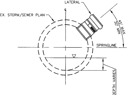
Figure 1 Cross Section Standard Tee
See Figure 2 for additional information on standard clearances to install a new connection:
- Install connections perpendicular to the host pipe.
- Multiple connections to a single pipe segment are allowed only with a minimum of two feet between the outside edges of each tapping hole, including spacing for taps on the opposite side of the host pipe.
- A minimum of three feet between the tap and the outside of a MH is required.
- A minimum of one foot between the outside edge of a tap hole and the bell end of any pipe joint is required.
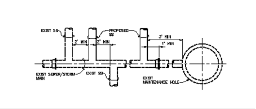
Figure 2 Tap Clearances, Plan View
For connections that do not meet these requirements for standard connections, see Section 10 Non-Standard Connections Process.
SPU is using INSERTA TEE® and Joints Tap-N-Tee® products for most cored connections. For these connections, SPU will install a tee and hub sized for either PVC or ductile iron laterals. With ductile iron lateral pipe, the contractor must supply a one-foot plain end by plain end pipe section or fitting for installation by SPU.
For contractor connections, the following is required for all tee products:
- Size tees per the manufacturer's recommended sizing for the specific host pipe size, material, wall type and thickness and for the lateral pipe size and material.
- Core the exact hole diameter per the manufacturer's recommendations.
- SPU observer must be present to see and confirm that the coupon is removed and the tee connection is installed correctly.
- Install per the manufacturer's recommendations, including any lubrication. Do not over insert. Loose connections or lateral pipe protruding into the host pipe by more than ½-inch will be rejected and the proposed fix must follow Section 10 Non-Standard Connections Process.
- For ductile iron lateral pipe connections, insert a one-foot plain end stub or fitting in the bell end tee. Connect lateral pipe to the stub using a shielded flexible coupling. See Figure 3.
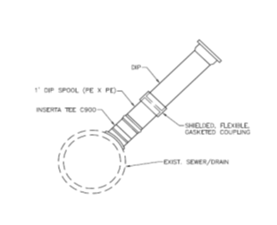
Figure 3 Ductile Iron Lateral Connection
9.1 Connecting to Clay Pipe with Mortar Joints (old clay)
Make connections to clay pipe by coring a hole and installing a tee when the host pipe is not cracked, or, if cracked, has been lined. Mounting the coring equipment requires access around the pipe.
Alternate 1, install a new manufactured clay tee by cutting out a section of the host pipe and installing a new section with a tee or wye. Make connections to the host pipe at a smooth vertical cut, butted closely to the new clay using a shielded flexible gasketed repair coupling to hold it in place. Ensure the host pipe inverts between new and old pipe are smooth. See Standard Specifications 7-17.3(2)E Jointing-Break-Out And Reconnect And Mismatched Wall Thickness and 9-05.18 Couplings For Pipe Jointing.
Alternate 2, see Section 11 Non-Standard Connections That SPU May Approve on the use of saddle wyes and tees.
9.2 Connecting to Clay Pipe with Compression Joints (new clay)
Make connections to clay pipe with compression joints by coring a hole and installing a tee.
For pipe less than 24-inch diameter, mounting of the coring equipment requires access around the pipe.
For pipe 24-inch diameter and larger, coring equipment will need a different secure point to steady the coring equipment.
9.3 Connecting to Concrete and Reinforced Concrete Pipe
Make connections to concrete and reinforced concrete pipe, including lined pipe, by coring a hole and installing a tee.
For pipe less than 24-inch diameter, mounting of the coring equipment requires access around the pipe.
For pipe 24-inch diameter and larger, coring equipment may be attached with studs, using anchor bolts, per the manufacturer's instructions. Maximum drilled hole size for anchor bolts is ½ inch and maximum depth of hole is 1 ½ inch. Remove bolts flush with the pipe. Fill any holes with mortar.
9.4 Connecting to Concrete Box Culverts and Horseshoe Shape Pipe
Make connections to box culverts, on the side of the box at mid-height and above. For connections below mid-height and to the top of the box, see Section 10 Non-Standard Connections Process.
Make connections to a horseshoe shape pipe at 45 degrees off the center top. See Figure 4.
Mark the host pipe with the outside diameter of the spigot end of the pipe to be grafted. And, then draw a square measuring 1 ½ inch wider (maximum) on both sides of the pipe springline. Cut out the square starting with the bottom cut and ending with the top. Angle each cut so that the interior of the square is smaller than the outside to prevent the removed pipe section from falling in. See Details A and B of Figure 4. Exercise care to prevent overcut, which will damage the pipe. In the case of an overcut, submit a mainline repair method to SPU Engineering for approval.
Alternatively, core tap the host pipe or culvert. Attach coring equipment with studs and use anchor bolts following the manufacturer's instructions. Maximum drilled hole size for anchor bolts is ½ inch and maximum depth of hole is 1 ½ inch. Remove bolts flush with the structure. Fill any holes with mortar.
Connect to the concrete by grafting a tee, using a ductile iron bell (Class 50 minimum) field cut so the length is flush with the inside mainline surface. Contractor is responsible to supply the bell and field cut to length which SPU will install.
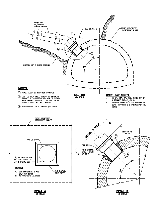
Figure 4 Connecting to Horseshoe Shape
9.5 Connecting to Ductile Iron Pipe
Make connections to ductile iron pipe by coring a hole and installing a tee.
For pipe less than 24-inch diameter, mounting of the coring equipment requires access around the pipe.
For pipe 24-inch diameter and larger, coring equipment will need a different secure point to steady the coring equipment.
Alternate 1, install a saddle-type tapping tee. Installation requires access around the pipe and cleaning of the host pipe to ensure continuous contact with the straps. Document that the torque applied to the saddle straps matches the manufacturer's recommendation.
9.6 Connecting to PVC Pipe
Make connections to PVC pipe by coring a hole and installing a tee. Mounting of the coring equipment requires access around the pipe.
Alternate 1, install a new manufactured PVC tee by cutting out a section of pipe and installing a new section with a tee or wye. Make connections to the host pipe at a smooth vertical cut, butted closely to the new PVC using a shielded flexible gasketed repair coupling to hold it in place. Ensure the host pipe inverts between new and old pipe are smooth. See Standard Specifications 7-17.3(2)E Jointing-Break-Out And Reconnect And Mismatched Wall Thickness and 9-05.18 Couplings For Pipe Jointing.
9.7 Connecting to HDPE Pipe (Solid Wall, Ribbed, Steel Reinforced)
For connections to HDPE host pipes, see Section 11 Non-Standard Connections That SPU May Approve.
9.8 Connecting to Polypropylene Pipe
For connections to polypropylene pipe, see Section 11 Non-Standard Connections That SPU May Approve.
9.9 Connecting to Brick Pipe
See Figure 5. For core taps larger than 12-inch diameter, also see Section 11 Non-Standard Connections That SPU May Approve.
For connections to an existing brick sewer, use this order of preference:
- Use existing wyes/tees to eliminate the need for a new tap;
- Cut in around an existing wye/tee to avoid an additional hole in the main;
- Cut in a new square. See Details A and B of Figure 5.
- Core tap a two-layer brick pipe. Secure the tapping machine by using anchor bolts following the manufacturer's instructions. Maximum drilled hole size for anchor bolts is ½ inch and maximum depth of hole is 1 ½ inch. Remove bolts flush with the structure. Fill any holes with mortar.
Connect to the brick sewer by grafting a tee using a ductile iron bell (Class 50 minimum) field cut so length is flush with inside mainline pipe surface. Contractor is responsible to supply the bell and field cut to length, which SPU will install.
The contractor shall excavate to expose a minimal area on the brick pipe and hand dig within 18-inches.
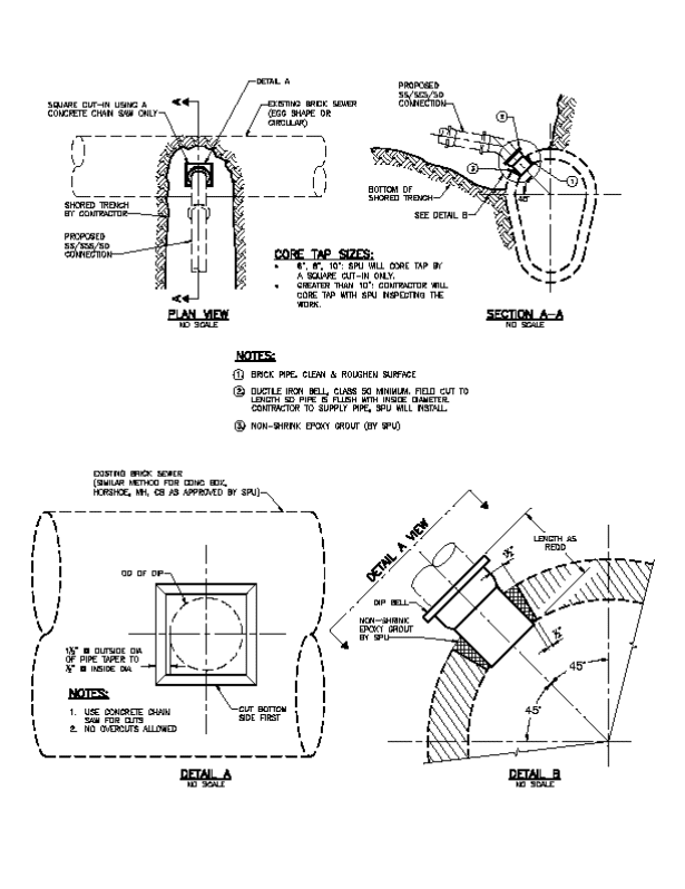
Figure 5 Connecting to Brick Pipe
9.10 Connecting to Asbestos Cement (A/C) Pipe
Connections to A/C pipe require special methods for removal and disposal.
The contractor is responsible for excavating material from around the pipe, using extreme care to avoid any abrasions to the A/C pipe. Size the excavation to allow the use of hand tools and removal of approximately two feet of pipe.
SPU will core a hole and install a tee. Or, alternatively, install a new pipe section (either clay or ductile iron) with a service tee.
SPU will dispose of asbestos material from the service connection activity.
9.11 Connecting to Corrugated Metal Pipe
The connection must meet Standard Plan No. 279. SPU will order parts to build the tee.
9.12 Connecting to an Existing Vertical (Or Standing) Connection
Existing standing connections were typically built with wye(s) to allow for a connection. For new connections, SPU will install a new PVC wye at one foot minimum from an existing joint. SPU may elect to extend the standing connection to the surface per Standard Plan No. 234. Connecting to existing wyes is not a new connection, but SPU may elect to extend to the surface while the excavation is open.
9.13 Connecting to Ditch and Culverts
When feasible to install a tee on the existing culvert above springline, connections to culverts will follow the standard for connecting to the culvert pipe material. When not feasible, connections to shallow street culverts will be by junction box installed by contractor. Junction box must be per Standard Plan No. 277.
See Section 11 Non-Standard Connections That SPU May Approve, for non-standard angles of connections when a junction box is not feasible.
Taper connections to a ditch to match the ditch grading and armor the connection to prevent erosion. SDCI, SDOT or SPU will perform the inspection. It is not necessary to schedule a core tap.
Non-standard connections are subject to additional review by SPU and will not be approved by SDCI or SPU field staff. SPU acknowledges that< this is inconvenient and urges all permit holders to plan ahead and consider potholing when the service lateral may be in conflict with other utilities.
Note that a non-standard connection may result in additional requirements or conditions for permitting the upstream lateral pipe.
SPU assumes that lateral pipe will be laid starting downstream at the tee. SPU will not consider upstream pipe laid out of sequence as a reason to allow a non-standard connection.
The permit holder must submit plan, profile and details to describe the proposed non-standard connection to the SDCI Side Sewer and Drainage Counter (206) 684-5362. A short narrative explaining the reasoning for the request is helpful, but not required. SDCI will coordinate with SPU for approval or disapproval of the request. Assume 5- business days for review. If the request for a non-standard connection is approved, SDCI will issue a side sewer permit, or an amended side sewer permit, documenting the allowable connection in the permit description. The permit holder can then proceed to scheduling.
Requests for a non-standard connection made after excavation will be evaluated by following the non-standard connections process and, if approved, issuing an amended side sewer permit. Contractors in this situation should:
- Take all necessary measurements and plate the excavation to allow traffic restoration.
- Cancel any scheduled core tap.
- Notify SDCI and SDOT inspectors of the delay.
- Draw a plan, profile and details for the proposed solution.
- Submit drawings to SDCI requesting an amended permit.
The following non-standard connections may be approved when SPU agrees that a standard connection is not feasible.
11.1 Non-Standard Angle of Connection
SPU will consider proposals for any angle of connection between 0 degrees at springline and a vertical connection at 90 degrees above springline. Submitted drawing must include the proposed profile and the measured clearances and elevations of utilities that are preventing a standard angle of connection.
11.2 Installing a New Maintenance Hole (MH)
SPU will consider proposals to install new MHs only under limited conditions. For SPU to consider installation of a MH, the following conditions must be met:
- SPU must agree that reducing the size of the lateral or splitting the flow to allow for a standard connection is not feasible. The permit-holder should submit all sizing calculations for review.
- The MH must be properly sized to meet Seattle design standards and constructed per the City of Seattle standard plans and specifications.
- The lateral must match crowns with the mainline pipe, unless SPU has approved a new inside drop connection per Standard Plan No. 233b.
- The contractor will install the MH.
- The contractor is responsible for scheduling SPU coordination and inspection prior to the start of excavation.
11.3 Connecting to an Existing Maintenance Hole
SPU will consider proposals to connect to existing MHs only under limited conditions. For SPU to consider connection to an existing MH, the following conditions must be met:
- SPU must agree that a standard connection is not feasible or desirable
- Connections must conform to Standard Specification 7-05.3(1)O.
- The existing MH is protected from damage, including uneven lateral loading when excavating along one side. Particular care is required to prevent uneven loading of brick structures. Damaged MHs must be repaired or replaced, at the discretion of SPU; and
- The lateral shall match crowns with the mainline pipe, unless SPU has approved a drop connection; and
- The existing MH shall be rechanneled by the contractor; and
- The ladder shall be replaced in accordance with Standard Plan No. 232.
- The contractor is responsible for scheduling SPU to cut-in on the structure or observe contractor cut-in on the structure.
11.4 Connecting to an Existing Catch Basin (CB) or CB connection pipe
SPU will consider proposals to connect to existing CBs only under limited conditions. For SPU to consider a connection to an existing CB, or a CB connection pipe, the following conditions must be met:
- SPU must agree with the following:
- Existing constraints make construction of a standard connection not feasible or desirable; and
- Only drainage will be discharged, not wastewater; and
- Failure of the new connection, associated with the failure or plugging of the existing CB and/or CB connection, does not create a public hazard, or risk of property damage; and.
- The capacity of the CB connection to meet its primary function of draining the street is not compromised.
- A new tap on the CB structure will be above the outlet invert or a new wye will be downstream of the CB structure.
- The contractor is responsible for scheduling SPU to cut-in a tee or observe the contractor cut-in on the structure or install a new wye on the CB connection pipe.
11.5 Roll-In a Large Lateral
SPU will consider proposals to install a large lateral under limited conditions. For example, an 8-inch by 8-inch manufactured tee. To consider a large lateral roll-in, the following conditions must be met:
- SPU must agree that flow splitting and standard coring of the mainline is not feasible or desirable.
- The large lateral fitting has a manufactured tee appropriate for matching to the host pipe material, which is uncommon.
Make connections to the host pipe at a smooth vertical cut, butted closely to the new tee using a shielded flexible gasketed repair coupling to hold it in place. Ensure the host pipe inverts between new and old pipe are smooth. See Standard Specifications 7-17.3(2)E Jointing-Break-Out And Reconnect And Mismatched Wall Thickness and 9-05.18 Couplings For Pipe Jointing.
11.6 New Vertical Connection
New vertical connections are often considered a tee, and not part of the lateral. So, SPU will typically approve new vertical connections on mainlines more than 20 feet deep. SPU will also consider installation of a vertical service connection when the following conditions are met:
- SPU must agree that a standard connection is not feasible or desirable.
- The vertical connection will be per Standard Plan No. 234.
- The drawing will clearly identify the ownership of the vertical pipe as a private side sewer (SS, SSS or SD) when appropriate.
11.7 Larger than 12-inch Connection to Brick Pipe
Connections larger than 12-inch to a brick host pipe must not rely on the brick pipe for support of the core tapping machine. An engineered plan for CDF or concrete support of tapping equipment is required. If the brick is single wall, or otherwise compromised, a plan for internal support may also be required.
11.8 Connecting with a Saddle Wye or Saddle Tee
Install a manufactured saddle wye or saddle tee designed to fit the outside diameter of the host pipe. Fully expose and clean the host pipe to ensure continuous contact with the straps. Install the saddle fitting following the manufacturer's instructions. Document that the torque applied to the saddle straps matches the manufacturer's recommendation.
11.9 Connecting to Polypropylene Pipe
Identify the profile wall type and thickness before ordering a manufactured tee product. The contractor is responsible for meeting the requirements of Section 8 Pipe Materials, Hole Size, and Selecting Tee Products and installing the tee.
11.10 Connecting to HDPE (Solid Wall, Ribbed and Steel Reinforced)
For connections to solid wall HDPE, submit a plan for a fused saddle connection per the Manufacturer's instructions. The contractor is responsible for meeting the requirements of Section 8 Pipe Materials, Hole Size, and Selecting Tee Products and installing the tee.
For connections to ribbed HDPE, submit a shop drawing specifying the tee product designed for the pipe wall type and thickness. The contractor is responsible for meeting the requirements of Section 8 Pipe Materials, Hole Size, and Selecting Tee Products and installing the tee.
New connections to steel reinforced HDPE detention pipe must be made by the original pipe manufacturer.
11.11 Connections made within a tunnel
When the lateral sewer and the connection will be made within a tunnel, the contractor must submit a proposal for installing a tee and documenting the installation for SPU observation without entering the tunnel. The proposal must document how the tee installation will meet the requirements of Section 8 Pipe Materials, Hole Size, and Selecting Tee Products. The contractor is responsible for installing the tee once the proposal is accepted by SPU.
11.12 Connections through a Casing
SPU will consider proposals to connect to a pipe inside a casing only under limited conditions. Casing pipe can be a variety of materials, but most typically will be steel pipe and the annular space between the carrier pipe and the casing may or may not have been filled with a flowable cement. Connections through a casing are difficult and damage to the casing is unavoidable. So, for SPU to consider installation through a casing, the following conditions must be met:
- SPU must agree that a standard connection is not feasible or desirable.
- Remove approximately an 18-inch square of casing pipe and chip out any fill within the annular space.
- Install the tee.
- Bed the newly exposed carrier pipe is bedded with Mineral Aggregate Type 6, 7 or 9.
- SPU may require repair of the casing.
Connections to force mains will not be approved.
Connections of lateral pipes with a diameter larger than the mainline pipe will not be approved.
Or, for example:
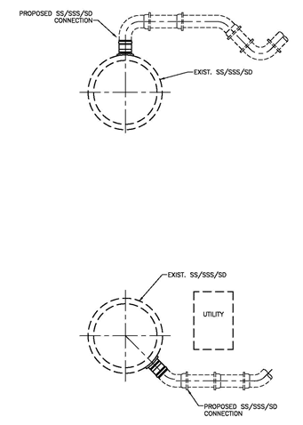
Figure 6 Examples Profiles -Not Approved
When the permit requires abandoning a tee or wye at the sewer or storm main, the contractor must install:
- T-cone mechanical stopper by Mission Rubber or approved equal in a clay, PVC, or cast iron tee or wye.
- Manufactured cap for ductile iron or cast iron pipe.
- Concrete Cap on concrete or reinforced concrete pipe.
Mechanical expanding stoppers made of metal and inflatable stoppers are only approved for temporary use.